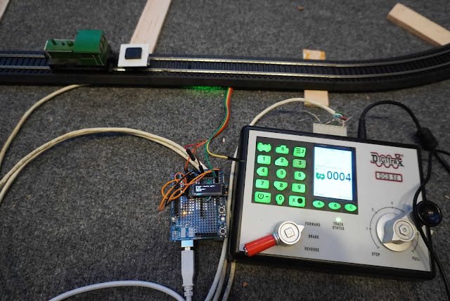
DCC Speed Matching Assistant Scratch Build
This project was inspired by some discussion over at https://modelrailroadforums.com/forum/index.php?threads/speed-matching-locomotives.35010/#post-543957
Overview:
- Create a simple car that can be attached to any locomotive and used to obtain speed matching data.
- Arduino based with no need for a computer attached but possibility to integrate with DCC possibly through I2C.
Speed = Distance / Time
Parts:
Hopefully you will already have a lot of these parts.
- 9" straight section of Bachman EZ Track or similar. + enough track to get the engine to the desired speed.
- Arduino Uno/Nano
- 1306 LCD Screen (128x32 pixels).
- Train throttle (DC or DCC)
- Train engine
- Car:
- Styrene sheet. I used a "For Sale" sign (Lowes) with a 0.015" thickness
- 3/32" (2.4mm) round styrene tube Evergreen Scale Models #223
- 1/8" (3.2mm) round styrene tube Evergreen Scale Models #224
- 5/32" (4.0mm) round styrene tube Evergreen Scale Models #225
- 3/16" 4.8mm) round styrene tube Evergreen Scale Models #226
- 7/32" (5.5mm) round styrene tube Evergreen Scale Models #227
- 1 Truck (Accurail) and wheels set (Walthers)
- 1 coupler (Accurail) with draft box (Kadee)
- 1 screw to hold on trucks. (Accurail)
- Extra car weight (Amazon)
Arduino Program:
Use an array of integers to hold readings sensor readings. This is averaged to prevent wild reading fluctuations.
Startup:
Collect an average of readings a startup.
Set a threshold just below the average.
Display the average and threshold to the screen or serial connection.
Program Loop:
- Read a sensor value the index value of the integer array.
- Get the average of all readings.
- If the average is below the threshold and the start time is zero then get the start time.
- If the average is above the threshold and the start time is not zero then get the stop time and calculate the speed using distance and time. Display the new speed and duration to the screen.
- Increment the index to the next sensor slot. Use modulus division to keep the counter within the size of the array.
Program Code:
The program may be found at https://github.com/awoehler/DCC-Speedometer
Physical Arduino Setup:
- Mount the trucks on the square with the piece that we just made below the truck. This will be the piece that is closest to the infrared detector. Foil tape can optionally be place on this to increase the reflectivity.
- Cut a hole between the ties just behind the nail hole. This is where the infrared detector/emitter will go. Hot glue to the bottom of the track.
- Connect the VCC on the sensor to 5V on the Arduino.
- Connect the GND on the sensor to GND on the Arduino.
- Connect the Digital out on the sensor to A0 on the Arduino.
- Connect the 1306 (128x32 pixels) screen to the Arduino. (Optionally you can use the Serial Output for reading your data.)
- Upload the sketch.
- Run trains.
- Adjust the pot on the sensor to match your lighting situation.
 |
| Top View |
 |
| Bottom View |
Car Directions:
- Cut a 9' 6" square for the base of the car.
- Draw a lines from corner to corner to find the center.
- Cut a piece of Styrene tube long enough to hold the wheels off the truck and glue to the center of the square. The combination of rods used as standoff's for the trucks will vary depending on the trucks that you use.
- Use a 3/32 styrene rod to mount the Kadee draft box to the center edge of one of the edges of the square. Glue scraps of styrene sheet to the edge to keep the draft box from twisting.
- Cut a piece of styrene (?) wide and (?) long so that it fits between the wheels. This will be cut into 1 long piece of 33.1mm, and 2 at 20mm. Glue the 33.1mm pieces and 1 20mm piece together. Drill a hole large enough so that the screw head can pass through it. Drill a hole in the second 20mm piece so that only the threads pass through. Now glue it to the other 20mm piece so that it looks like this.
 |
| Side View |
 |
| Top View with automotive wheel weight installed. |
 |
| Bottom view. I added foil tape to try and increase the values when driving over but it didn't make much difference. The bump in the center is the screw that holds it together. |
 |
| Coupler end view. I used Accurail couplers with a Kadee draft box as I have extra and didn't want to use up my Kadee couplers on this. |
 |
| Back end view. The vertical piece stabilizes the reflector on the bottom so that it does not twist and rub against the wheels. |
Notes:
When the sketch starts up it fills the array of will values from the current reading so you will not want anything over the sensor when it starts.
Initially I used the analog output but when when I changed lighting situations it was less dependable.
The timer will overflow or wrap around at about 50 days so I'm not sure what will happen if you leave this on for a long time.
As the train goes faster the readings become less accurate because the time becomes smaller and smaller, increasing the length of the car could help to resolve this. The length of the car can be adjusted at the top of the code.
Conclusion:
This has been a fun little project. One of the advantages for this method is that it is non-directional so it makes the code easier to implement. I don't think it is very accurate though using the analog reads to determine the timing. I would like to create an interrupt version of the code to see if it is more accurate. If/when I get around to that you should find that version in the github code. At this point it has not been integrated into DCC/JMRI. I think that would be fairly trivial for someone familiar with the code base. But for now I'll at least share this code.
If you have questions or comments I would encourage you to join the discussion over at https://modelrailroadforums.com/forum/index.php?threads/speedometer-build-log.35066/#post-546129


Comments
Post a Comment